300+ km/h Quadcopter Speed Drone
My roommate is building a jet-powered RC plane and chasing supersonic. I wanted my own speed project, so I picked something quadcopters are bad at: going fast. The target was 300 km/h, and I spent last summer designing toward it. First print came off on August 25th, and on September 16th it flew 325 km/h on GPS. Twenty-two days, print to 300.

Skills
- SolidWorks
- OpenFOAM (CFD)
- ParaView
- 3D printing (PLA)
- Soldering
- ArduPilot
- PID tuning
- Flight testing
The airframe
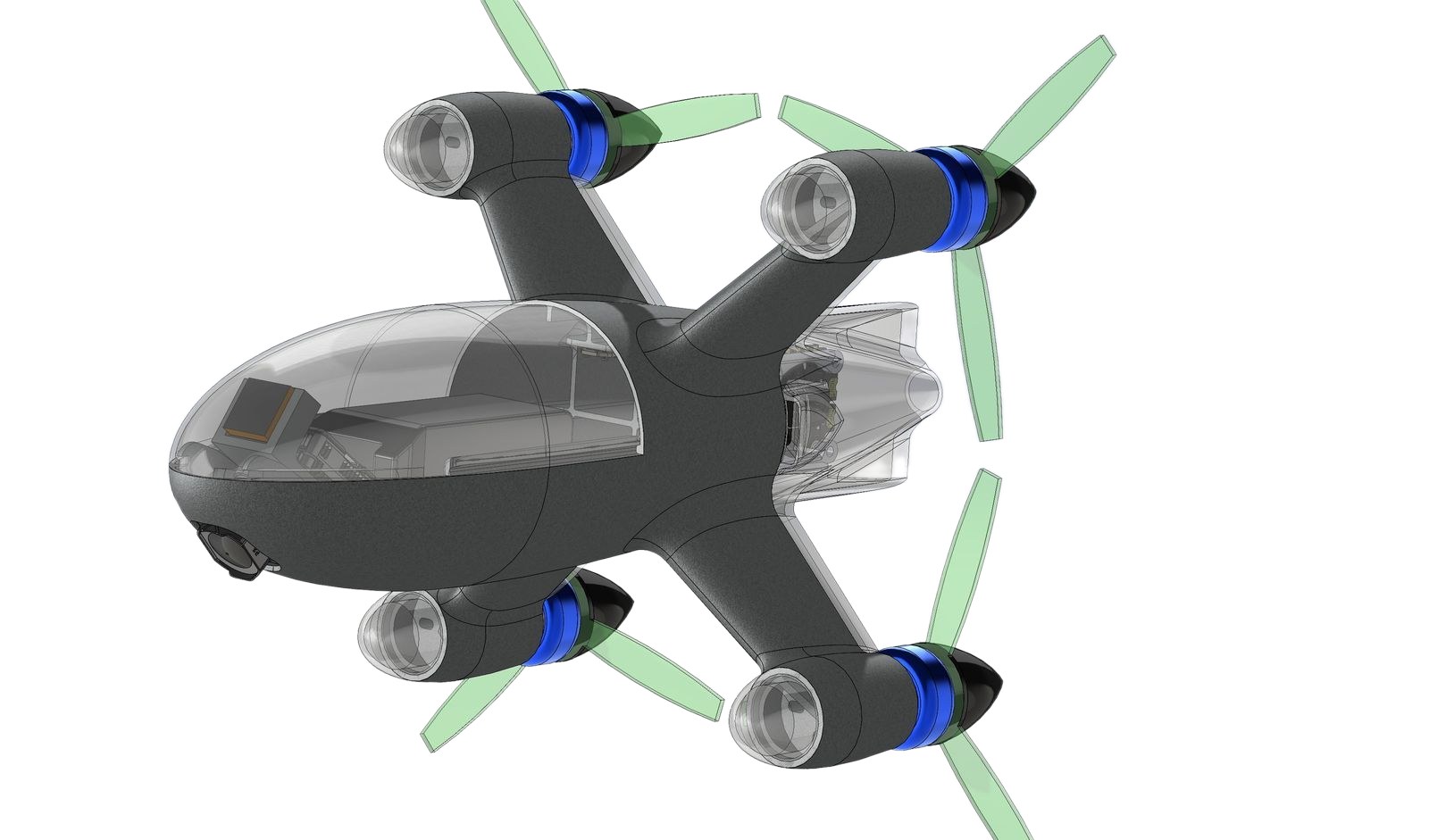
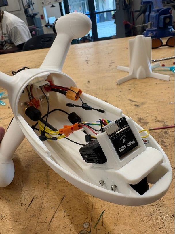
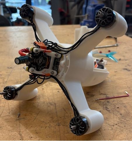
A normal 5-inch race quad is a flat carbon X with the battery strapped on top and everything exposed. Pitched nose-down at speed, all of that blunt hardware sits right in the airflow. So I designed it the other way round. One streamlined fuselage holds the battery, stack, GPS and camera, with faired motor pods and tail fins. The body only fits what it has to carry.
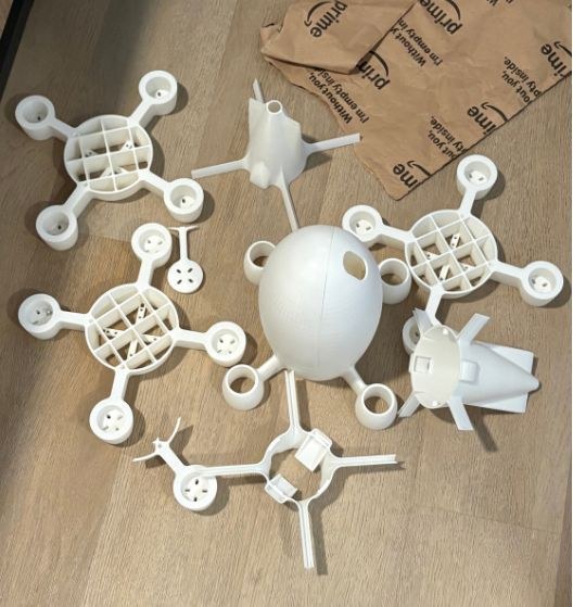
I printed it in PLA on my Bambu Lab A1. People raise an eyebrow at that, but PLA is stiffer than PETG, and at these speeds flex in the arms shows up directly in the flight controller. It also prints accurately enough that the stack and GPS mounts came out right without shimming. The tradeoff is heat. PLA softens around 55 to 60°C, so the fuselage has scoops feeding cooling air over the ESC, and the drone stays out of direct sun between flights.
What the CFD said
I ran the airframe in OpenFOAM from −4° to 13° and 10 to 100 m/s, then worked through the results in ParaView. The fiddly part was meshing around the motor pods. My first meshes either refused to snap or blew up the cell count, so I put tight refinement boxes around the pods and the nose and left the rest coarse. High angles near 12° converged last, which made sense once I saw the flow separating there.
The runs used [TODO: turbulence model] on a mesh of [TODO: cell count] cells, and the props were [TODO: modeled or not modeled]. I have not written up a mesh-independence check [TODO: mesh-independence result, or that I didn't run one].
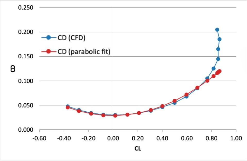
That 0.029 is not the same CD as the body numbers below. The polar uses [TODO: reference area for C_D0]. The body totals, 0.127 and 0.144, and the camera pair, 0.109 and 0.172, use [TODO: reference area for the body C_D values]. The viscous and pressure splits sit inside those body totals. They are not pieces of the polar.
My favourite shape going in was a longer, lower body. It looked much faster. It was slower. The extra length added surface area, so viscous drag rose from 0.036 to 0.041, and the tail junction separated earlier, so pressure drag rose from 0.091 to 0.102. Looks sleek and low drag turned out to be different things. I kept the shorter body.
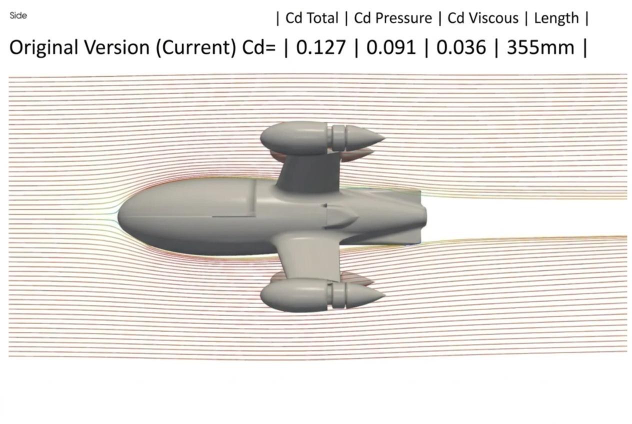
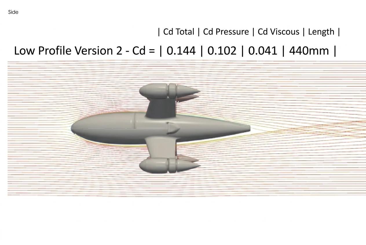
Two more numbers mattered. The camera cutout alone takes CD from 0.109 to 0.172 on a like-for-like body, a 58% penalty for one hole in the nose. The built body lands at 0.127 because the final cutout is faired in. Drag power at 325 km/h, drag times velocity off that polar, is about 1.3 kW. Electrical power at the motors is higher once propeller efficiency is included [TODO: prop efficiency, or measured electrical power at 325 km/h]. Installed electrical power is 3.4 kW, so drag was still not what stopped it.
Build and flights
Everything inside is stock 5-inch freestyle parts, deliberately. Anything that breaks gets replaced the same day. Motors are iFlight XING-E Pro 2207 1800KV on 6S, the pack is an Ovonic 6S 1300mAh 100C picked for burst current, and video is a DJI O4 Pro. I did all the soldering myself. My original SpeedyBee F405 V4 stack died on the bench before the first flight, and the V4 was discontinued, so I moved to the F405 V5, learned its 32-bit ESC firmware from scratch and re-soldered the receiver onto a different UART. Days of work instead of weeks, which is exactly why the parts are stock.
It runs ArduPilot. [TODO: what I configured in ArduPilot]. I tuned the PIDs [TODO: which gains I changed, and what the quad did after]. If I can't fill either of those in, both skills come off the list.
I test in the open [TODO: field], with a spotter [TODO: who], and the aircraft is [TODO: FAA registration number, or not registered].

172 km/h at 48% throttle showed the drone was fast. It did not check the CFD. Two flights later, flat out, the GPS read 325.
The props are the obvious ceiling, and I don't have the rpm to show it. Unloaded, 1800KV on a full 6S pack at 25.2 V is about 45,000 rpm, which puts 4.6-inch pitch at roughly 318 km/h. Under load the pack sags and rpm drops, so 325 km/h would be well past pitch speed, not sitting on it. A tailwind could be in that GPS number too. [TODO: ESC rpm telemetry from the blackbox log on the 325 km/h pass]
Power check
[TODO: measured-vs-predicted power. Logged current and voltage at a known GPS speed, set next to the polar's drag power at that speed. Prop efficiency has to be in the comparison, or the two numbers are different kinds of watts.]
What's next
Max-thrust test on higher-pitch props first, then averaged speed runs, then autonomy on the onboard GPS.