4-Wheel Differential Swerve Robot
A four-wheel robot where every wheel sits in a differential swerve module: two motors per module both steer and drive the wheel, so the robot can move in any direction while rotating. I'm designing the mechanics, electronics and firmware myself.
Skills
- Fusion 360
- FEA
- Gear and mechanism design
- 3D printing (PLA)
- KiCad PCB design
- ESP32 firmware
- Motor control (PWM)
- Raspberry Pi 5
- LiDAR
- Design for assembly
Why differential swerve
In a normal swerve drive, one motor steers each wheel and another drives it. In a differential swerve module, two motors work together through a gear differential: turning them the same way drives the wheel, and turning them at different speeds steers it. Because neither motor rotates with the wheel, there are no wires to wind up, so each module can steer endlessly in either direction.
Mechanical design
I modelled the full assembly in Fusion 360 and 3D-printed every structural part in PLA. The robot has four modules on a four-piece printed chassis, with a 35 mm centre cap that houses the Raspberry Pi 5, the motor controller and the LiDAR mount. Each module has a ring gear held down by printed clamps, and a hall sensor that lets it find its home steering position on start-up.
Stress testing the gears
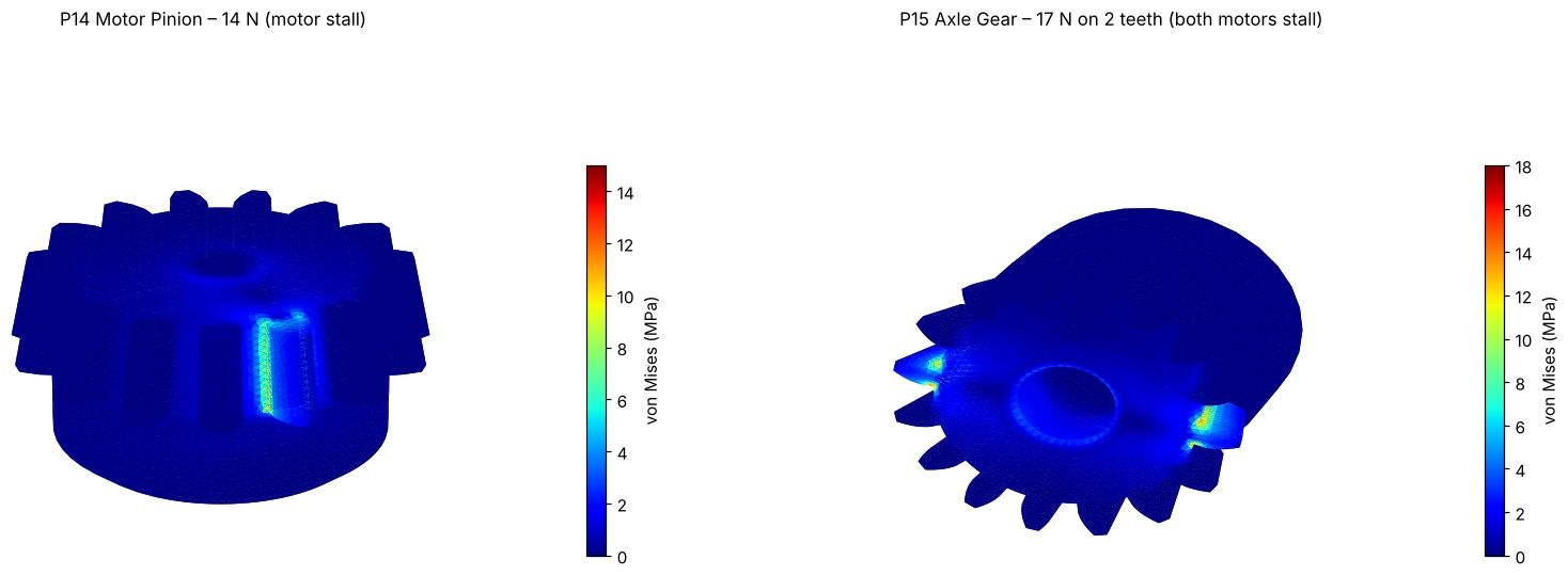
I ran FEA on the gears and bearing brackets at motor stall load, the worst case they will see. The peak stress came out at 12 MPa, comfortably below the roughly 50 MPa that PLA can take. I then refined the pinion bores, ring hold-downs and centre cap through several print-and-fit cycles until everything meshed cleanly.
Electronics and a custom PCB
The robot's work is split between two computers. A Raspberry Pi 5 handles LiDAR mapping and path planning, and sends commands over USB to an ESP32 that runs the eight motors and four hall sensors in real time. I wrote the ESP32 firmware, which drives the motors with 20 kHz PWM, homes each module using its hall sensor and saves calibration to flash.
My first plan used two hand-wired perfboards with dozens of solder links. Instead, I designed a single two-layer controller PCB in KiCad, autorouted it with Freerouting, checked every net against the firmware's pin map and sent it to PCBWay for assembly.
| Board | 88 × 33 mm, 2-layer |
|---|---|
| Drivers | 4× TB6612FNG, running 8 motors |
| Sockets | 8 motor + 4 hall sensor, JST-PH |
| Checks | 0 design-rule errors, 0 unconnected nets |
Where it stands
- All four modules and the chassis are printed.
- Test firmware is uploaded and running on the ESP32.
- Five assembled boards are in review at PCBWay.
What I learned
Write a few sentences here in your own words: the hardest part of the design, what the print-and-fit cycles taught you, and what you would do differently next time.
What's next
- Testing each module on the new PCB.
- Closed-loop steering and drive control.
- LiDAR mapping and autonomous path planning.